Introduction
This space is created to share information related to "ELECTENG 311: Electronics Systems Design" under a Creative Commons Attribution 3.0 Licence. The site contains a collection of lectures along with extra information such as example designs from previous years, code examples, design ideas, etc. The presentations are written in Markdown.
About ELECTENG 311
Electronic circuits, found in applications ranging from medical to consumer products to aerospace, require energy sources that are conditioned to specific forms to safely energize them. For example, to charge our mobile phone, we need to connect a regulated 5 V DC source to the charging port of the phone. The regulated voltage that is needed to power any electronic circuit is derived using a power converter. A power converter feeds from a raw energy source like a battery or an AC power outlet and generates a regulated output in the form that is accepted by the electronic circuit it powers. Typically, modern electronic devices employ complex circuitry requiring different voltage and power levels, and as such employ many power converters. Though simple low-power circuits employ liner-regulators as the power converters, switch-mode power converters are widely used in more demanding situations. Hence, it is vital to learn how a switch-mode converter works and be able to design one that meets a specific set of requirements.
In order to gain fundamental understanding of switch-mode power converters, during this project students will be designing and developing a pocket-sized power supply that could replace the bulky low-voltage power supply found on a typical work bench. The power supply would be fed from a USB-C PD capable port and its isolated output voltage is controlled by the user via a computer. Real-time information about the load attached to the power supply will also be displayed on the computer. To achieve this, students will be working as part of a design team of four students, who will undertake an investigation and subsequently design and develop a power supply that meets a set of specifications given.
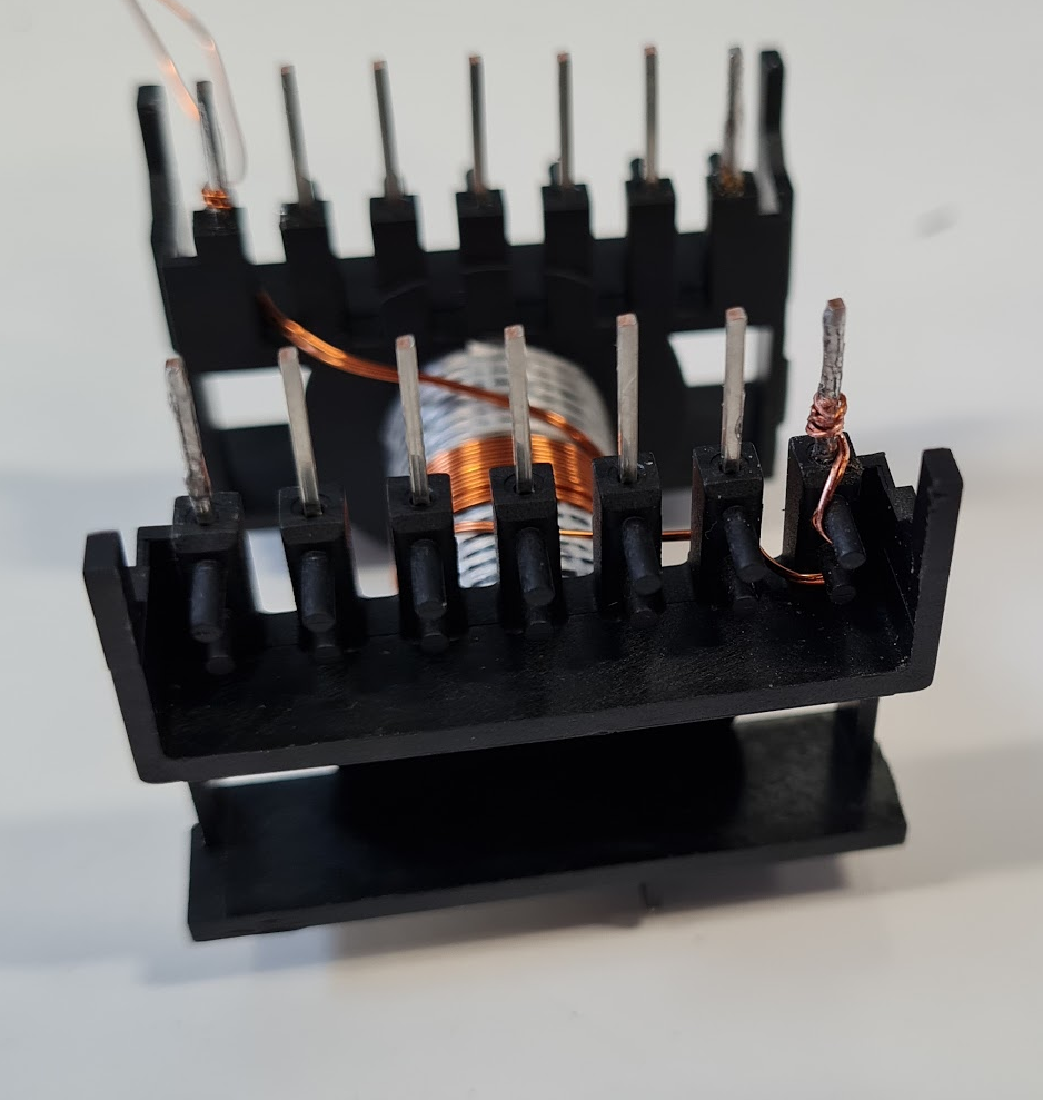
There are four components to this project - hardware design, magnetic design, firmware development, and system integration. Students will start the project by developing a ‘paper’ design of the hardware, and then validate this design using LTspice simulations. Students will then work on the magnetic design, which will be validated and improved using Ansys Maxwell. In parallel, using Proteus Virtual System Simulator (VSM) and the ATmega328PB Xplained Mini, students will develop and validate the firmware needed to control your power supply. Finally, hardware, magnetic and firmware designs will be integrated to develop a prototype power supply to characterise and show that it meets the given design specifications. At the conclusion of the project, each design team will be interviewed by an assessor and given the opportunity to demonstrate the performance of their design. The top designs will be judged by engineers from Fisher & Paykel Appliances, who sponsor this course, and the best design team will be awarded a prize.


